Trademark
Trademark

Fracture Imaging Analytics

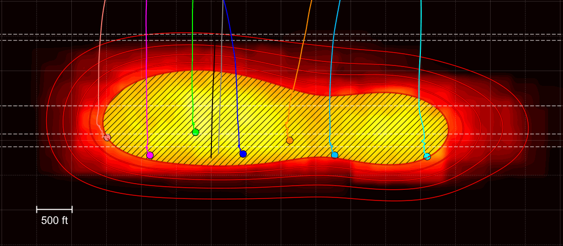
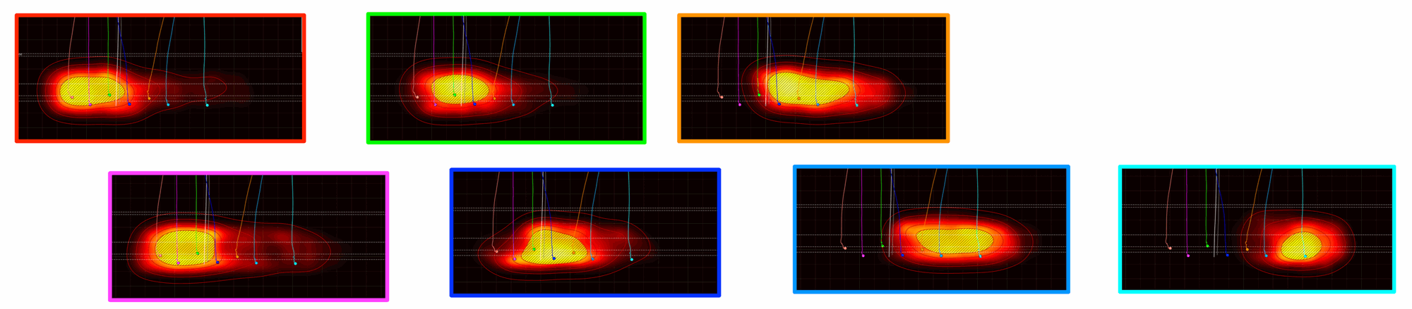
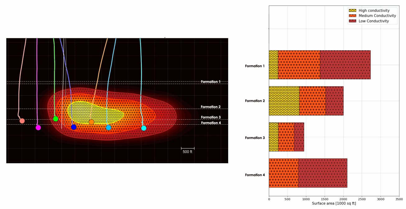
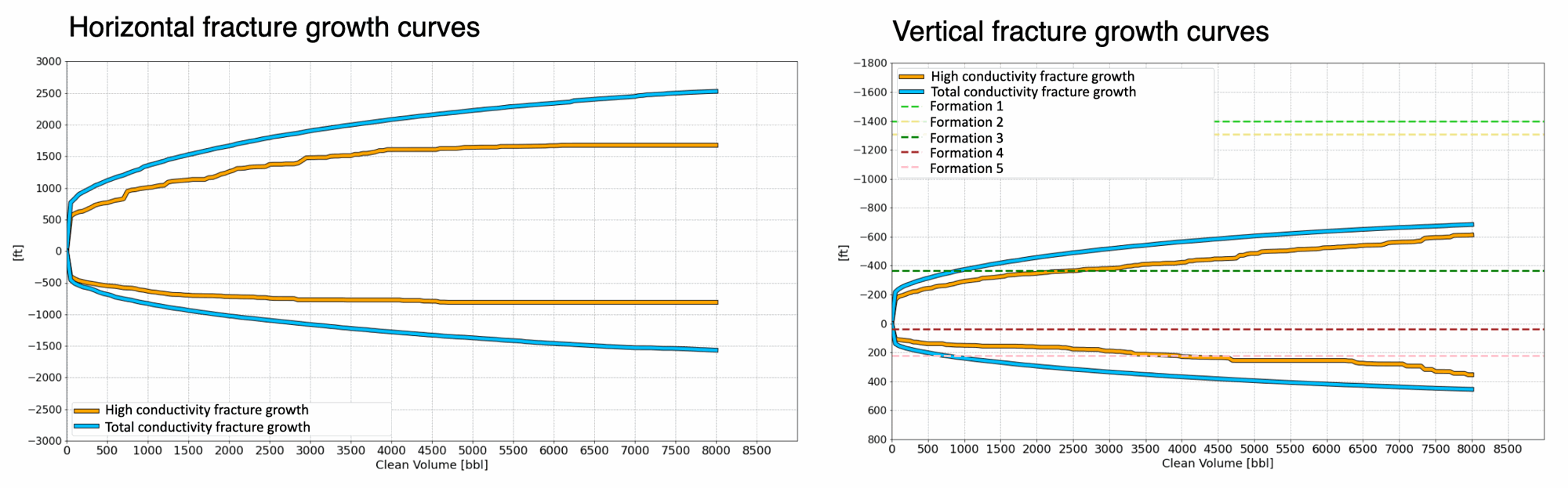
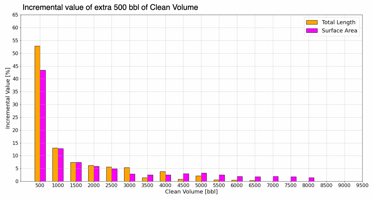
Analytics begins after imaging is complete. Using the fracture geometry and morphology results, we compute metrics that are directly relevant to field development. This work combines imaging output with additional data from the client such as treatment data, completion design groups, and other measurements like wellbore pressure.The analysis depends on the specific goals of the project. It usually starts with a defined set of questions, followed by additional requests as new patterns or features are identified. We work closely with the client throughout to ensure the results remain focused and informative.The sections below show examples of analytics we provide.

Cumulative Fracture Conductivity Maps (Gun Barrel Projection)

We compute fracture conductivity maps by stacking the 3D imaging results along the well trajectory. This can be done for all imaged stages or for selected stage groups, depending on the analysis goals. The result is a robust 2D map showing the relative fracture conductivity, as well as vertical and horizontal fracture dimensions. These maps represent the cumulative conductivity generated by stimulation of all completed wells, and provide an intuitive way to evaluate inter-well communication and overall completion effectiveness.
Cumulative Fracture Conductivity Map

Well-Level Fracture Conductivity Maps

Using microseismic data, treatment records, and the imaged fracture geometry, we construct fracture propagation models for each individual well. These models are combined with analytical solutions that describe how fracture conductivity decays with distance from the perforation clusters. This allows us to generate fracture conductivity maps at the well level. The sum of these well-level maps reconstructs the cumulative conductivity image shown in the previous section.
Well-Level Fracture Conductivity Map
Having these well-level fracture conductivity maps allows us to visualize and quantify key factors of fracture behaviour, including the effects of completion sequencing, depletion, inter-well communication, and fracture height containment. This level of detail helps operators understand how each well contributes to overall stimulation effectiveness and where interactions may be limiting performance.

Fracture Surface Area

Individual fracture conductivity maps also allow us to compute fracture surface area. Beyond total area, we distinguish zones of varying conductivity and compute surface area for highly conductive versus less conductive regions. These calculations can also be broken down by formation or stratigraphic zone, providing more insight into vertical fracture connectivity.
Fracture Surface Area segmented by formation

Fracture Growth Curves

By combining well-level fracture geometry, relative conductivity images, and fracture growth models, we compute horizontal and vertical fracture growth as a function of stage elapsed time or clean fluid volume. Growth curves can be generated for total fracture surface area as well as for the most conductive portions of the fracture network. These metrics provide a dynamic view of how the fracture system develops during stimulation.
Fracture Growth Curves

Incremental Value of Clean Volume

Our analysis quantifies the added fracture surface area and total fracture length gained per unit of additional clean volume. This can be evaluated at the well level or for specific completion design groups. These insights help operators determine the optimal clean volume per stage and adjust stage duration to maximize stimulation efficiency.
Incremental Value of Clean Fluid Volume